Models are built in the first work flow step named Model (see image below) using its different tools. The tools are located around the Model View. The available tools are:
- The Object panel in the top left corner.
- The Template panel in the lower left corner.
- The Variant panel in the top right corner.
- The Variable panel in the top right corner.
- The Flow panel in the middle to the right.
- The Property panel in the lower right corner.
- The Navigation panel above the Model View.
- The Log panel below the Model View.

Object panel ↑

Production flows are built using the objects available in the object panel. The object panel holds both flow objects (e.g. Operation, Buffer) as well as logic objects (e.g. Shift, MaxWIP). Objects are added to the modeling canvas by Drag n' Drop. Detailed object descriptions can be found here.
Template panel ↑

By using the template panel, custom components can be built using standard objects and previously created templates. Templates can be used to capture a certain production behaviour in one template that easily can be used in several locations of the production flow. They can also help in giving a better overview of the production flow by grouping sections of the production flow into a template, and thereby achiving a less cluttered top-level overview.
Created templates are added to the model by Drag n' Drop precisely as the standard objects. A more detailed descriptions of templates and how they are created can be found here.
Variant panel ↑

Variants that are to be processed in the production flow are added and then listed here. The special (always present) variant named Any Variant can be used as a 'wildcard' Variant to represent any of the Variants added in to the model. This can for instance be useful in Flows that should be valid for all Variants or in generic Assembly tables.

A variant is added by pressing the
 -button at the bottom
of this panel and typing a name for the new variant
in the dialog that appears, see image to the right.
A variant is removed by selecting it in this panel and pressing the
 -button at the bottom of this panel.
Several variants can be selected and deleted at a time.
Variable panel ↑

Model variables that can be used in Formulas throughout the model are added and then listed here. The variable will be listed with its name followed by its value surrounded by parentheses, like 'name_of_variable (value_of_variable)'.
Note: Model variables are not to be confused with Optimization Variables, even though model variables can be added as optimization input variables.

A model variable is added by pressing the
 -button at the
bottom of this panel and typing a name for the new model variable
in the dialog that appears, see image to the right.
A model variable is removed by selecting it in this panel and pressing the
 -button at the bottom of this panel.
Several model variables can be selected and deleted at a time.
Flow panel ↑

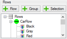
In the flow panel all production flows of the model are managed and once created they are listed in a tree structure. As implied, several production flows could be created. Variants are added to each flow by the user, i.e. a flow is only valid for the variants that the user adds to the flow. In this way it is very easy to, for example, model a common flow for all variants in part of the production and have each variant or groups of variants have separate flows in other parts of the production.
In additon to having several flows there is a option to create a flow selection and to group flows together in a flow group. This is used to easy model and evaluate different route/flow alternatives and can be extremely useful for use in complex optimization problems. A more in dept description of flows and all its features can be found here.
Property panel ↑

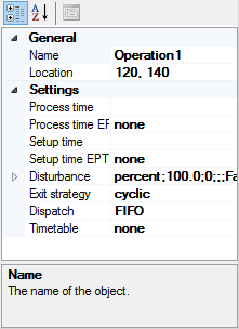
The property panel is were all input data of the simulation objects are set. The property panel shows the settings of the currently selected object(-s). When several objects are selected only settings that are present on all selected objects are shown. This multi-select feature enables the same settings to be made to several objects at once, which can be very convenient. The property panel and is features are described in more detail here.

The navigation panel is used to navigate in the model when it have several levels, i.e. uses custom components and/or object selections. It displays the full path of the object currently shown on the modeling canvas. Information of how it is used can be found here.
Log panel ↑

The log panel lists anything that is wrong in the model. Each log contain a path, type and text. The path is useful in determining the location of the error, whereas type and text is used to describe what is wrong.
Note: This panel is only visible if there is something wrong with the model.